Look a little closer
A zipper works because a Y-shaped channel inside the slider guides two separated rows of elements into precise engagement one pair at a time. Moving the slider the opposite way lets a central wedge divide the joined chain and release the elements sequentially. The slider does not fasten the entire length at once. It repeats a tiny assembly operation as it travels, converting one straight hand motion into hundreds of connections.
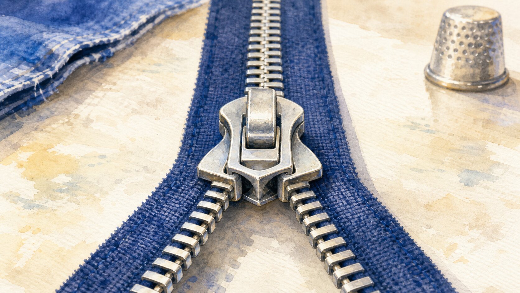
The basic parts are two fabric tapes, two rows of fastening elements attached along their edges, and the hand-operated slider. We call the elements teeth, but a metal zipper element is more like a miniature coupling with a projection and a receiving recess. The rows are offset rather than aligned directly face to face. An element from one side settles between neighbors from the other, producing a single alternating chain when closed.
Inside the slider is a central post, often called the diamond, surrounded by flanges and guide surfaces. At the open end, two broad channels admit the tapes separately. Toward the closed end, those paths converge into one narrow throat. As the slider moves in the closing direction, the side walls steer the rows inward while the top and bottom plates constrain element height and tilt. Elements leaving the central wedge overlap in a controlled sequence, fitting their projections and recesses together.
Opening uses the same geometry in reverse. The engaged chain enters the narrow stem, where the point of the central diamond advances between the rows. Continued motion directs each row outward along a different arm of the Y, releasing one coupling after another. A hand never has to pick apart individual teeth. Fixed internal surfaces determine their paths. In engineering terms, the slider functions as a traveling alignment fixture and wedge.
Once closed, a zipper does not rely on the slider pressing along its whole length. The slider has already moved away from most of the joined section. Interlocked projections and recesses resist the sideways pull on the tapes, while neighboring elements share the load along the chain. Because many small couplings sit on flexible tape, the joint can resist separation yet still bend along its length with clothing or a bag. Strength therefore depends on element geometry and spacing, attachment to the tape, material properties, and the seam that connects the tape to the product. The slider is the assembler, not a clamp covering the finished joint.
Small dimensional errors can defeat the system. A bent element or stretched tape changes the spacing required for a projection to find its matching recess. If the slider mouth wears and spreads, it may no longer bring the rows close enough, so the pull passes while the chain splits behind it. Fabric caught in the entrance applies an angled load; forcing the pull can further distort the slider, elements, or tape. Smooth operation is therefore about preserving alignment as well as overcoming friction.
Not every zipper consists of separate metal teeth. Molded plastic zippers form individual elements on the tape, while coil zippers use bends in a continuous synthetic filament as the coupling heads. Their flexibility, profiles, and environmental performance differ. They still share the broad principle that a fitted slider constrains two rows into or out of engagement in sequence. Because element and channel dimensions are a matched system, a similar-looking replacement slider may not work on another chain.
Open-ended jacket zippers add an insertion pin and retaining box to establish the first alignment. The pin must seat fully so the two rows begin in phase before the slider can create the first coupling. Some trouser sliders also contain a locking pin that catches an element when the pull tab lies down, preventing gravity and body motion from lowering the slider. Element engagement, bottom alignment, and pull-tab locking are separate functions solved by separate details.
A major step toward the modern design came when Gideon Sundback improved earlier bulky hook-and-eye fasteners during the 1910s. His system used dense facing rows of uniform coupling elements and a slider, documented in the 1917 U.S. patent for a 'separable fastener.' Materials and locking features have multiplied since then, but the central idea remains compact: store the required motion in the shape of each element, then let a Y-shaped guide execute that motion one position at a time.
EDITORIAL RESPONSIBILITY
FactosBrain Editorial Desk
The FactosBrain Editorial Desk researched and reviewed this article under our editorial policy. We assess error reports under our corrections policy.